How to turn a Vintage Zenith Radio Cabinet into a Lighted Bar Part 5: Door and Electronics
Hanging the Door
The original plan for hanging the door was to use a piano hinge. This seemed like a good idea at the time, but I had a heck of a time getting the swing of the door right. I think I ended up getting a couple of holes out of true, and then the door wouldn't close all the way.
I looked for solutions for a long time, and I finally settled on a wrap hinge. A wrap hinge would allow me to put the screws into the strongest part of the frame I built around the door opening, but it did require me to chisel out some hinge pockets.

Hinge pocket on the door, along with the holes from the piano hinge

Wrap hinge on the frame
I liked how the wrap hinges came out. The door still didn't quite close, but it was better, and I was planning on using a magnetic catch, so that is how I "fixed" it. Bre filled and re-painted my wood-butchery, and we were ready for the final stage!
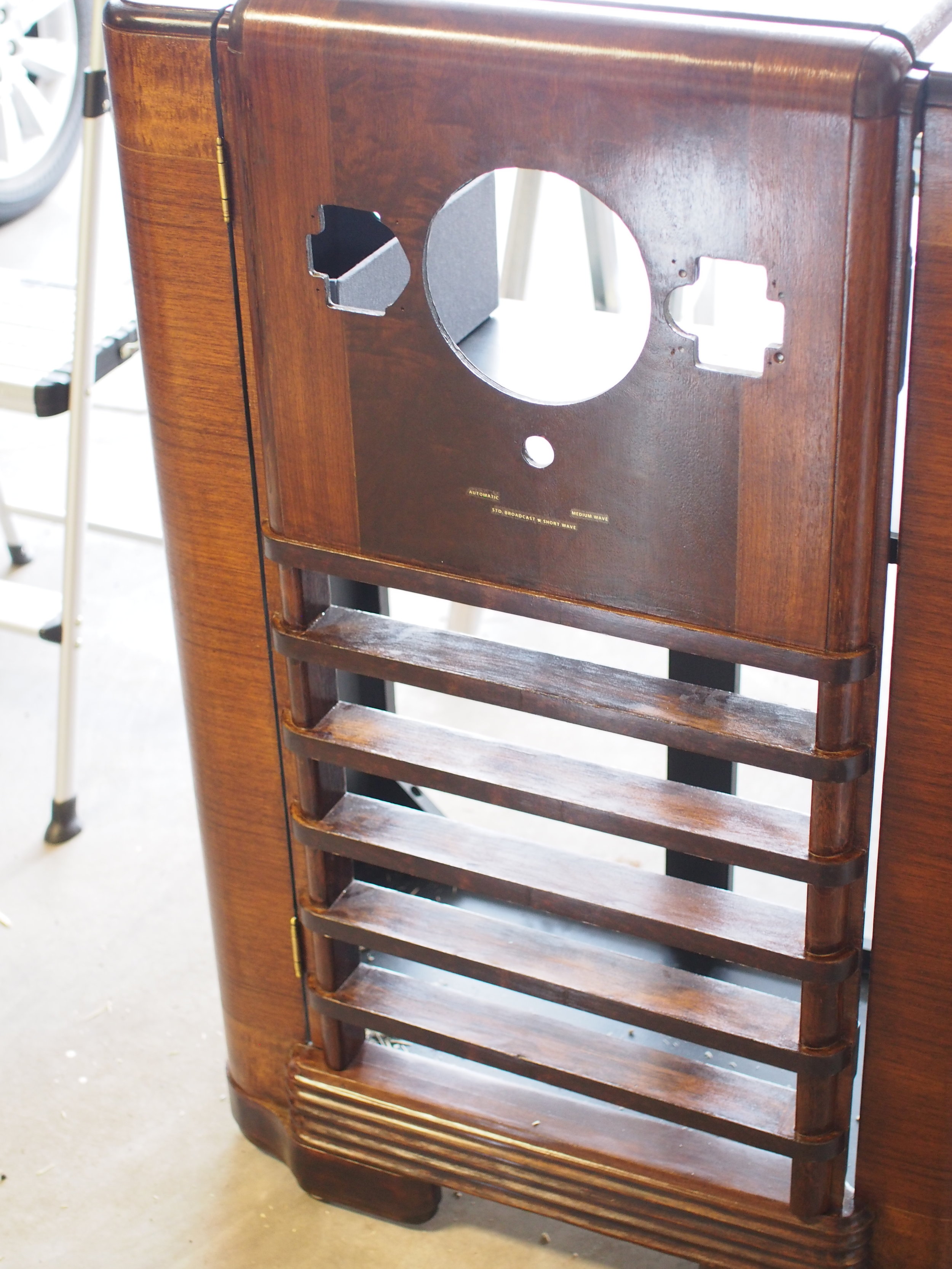
Door on. You can see the door still doesn't quite close.

The door with the back installed

Magnetic catch

The installed wrap hinges
Circuitry
I had pretty grand plans at the beginning. I originally wanted to make all the buttons on the front, like Bass and Treble and whatnot do things. I also wanted to light the interior, and integrate the main dial somehow. As I got into it, that turned out to be outside of my ability at present. I have a fair bit of experience with circuits and electronics, but I discovered my skills are pretty out of date.
I settled on using RGBW LED strips to light the interior. I bought my LEDs from Adafruit, since they had a nice tutorial on their site for building the circuit and programming an Arduino to run the LEDs.
I had some trouble with the microcontroller, which was entirely my fault. I was fooling around with the circuit while it was connected to my PC for easy code changes, but I had the LED strips powered off a separate power supply, since I didn't want to draw too much current from the USB port. That was a problem since the grounds weren't directly connected. I ended up burning up the first Arduino I bought, along with a couple of my power transistors.
Oh yeah, and I fried the 10K potentiometer I was using to test the dial function. I had the silly thing directly connected to the power supply, instead of the 5V output of my Arduino. I also discovered a short in my prototyping breadboard. The contacts inside were bent, causing the power and ground on the sides of the board to touch. This all came pretty close to being the final straw. We were over two years into the project at this point, with a lot of time and effort and false starts, and I couldn't build a circuit!
I ordered more parts, and started over. I scaled my plans back to something I could achieve, with the options to add more features later if I get ambitious. The feature I chose to focus on was to use the tuning dial to control the intensity of the LEDs. That wasn't quite what the Adafruit tutorial was about, but I found another tutorial with code I could copy. Here is where I am now:
int ledPin1 = 3;// LED connected to digital pin 3 int ledPin2 = 6;// LED connected to digital pin 6 int ledPin3 = 9;// LED connected to digital pin 9 int ledPin4 = 11; // LED connected to digital pin 11 int potentiometerPin = A2; void setup() { // initialize digital pins as outputs. pinMode(ledPin1, OUTPUT); pinMode(ledPin2, OUTPUT); pinMode(ledPin3, OUTPUT); pinMode(ledPin4, OUTPUT); pinMode(potentiometerPin, INPUT); } void loop() { int potValue = potentiometerValue(); int fadeValue = map(potValue, 0, 1023, 0, 123); // sets the value (range from 0 to 123): analogWrite(ledPin1, fadeValue); analogWrite(ledPin2, fadeValue); analogWrite(ledPin3, fadeValue); analogWrite(ledPin4, fadeValue); // wait for 30 milliseconds to see the dimming effect delay(30); } //function to calculate potentiometer value int potentiometerValue() { int val = analogRead(potentiometerPin); return val; }
All of the LEDs are modulated together. I have some features in this code what will allow me to separate out the color channels later if I feel like getting fancy with colors. I have also limited the power draw of the LEDs to only half of their scale with the fadeValue variable. In principle, it would go up to 255. But I was gun-shy after destroying my power transistors.
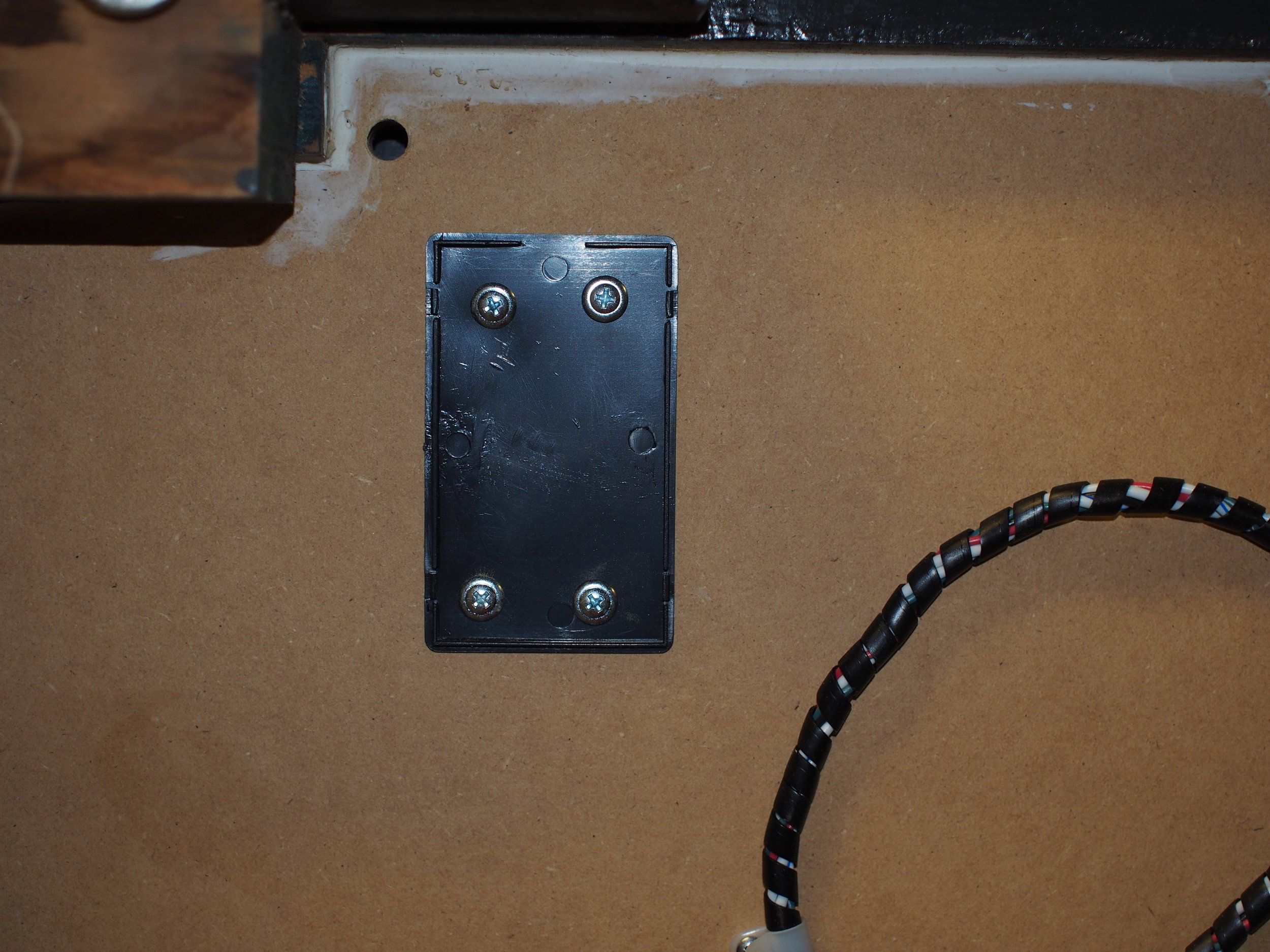
The case lid, along with the hole for the dial wires and the LED power leads
My circuit is based heavily on the Adafuit schematics. I bought some cases and screwed them to the bottom of the cabinet, and I put the Arduino and the breadboard in the cases. I used a 2.5mm barrel jack for the power supply, and crimped ring connectors to join the power transistors to the LED power leads.
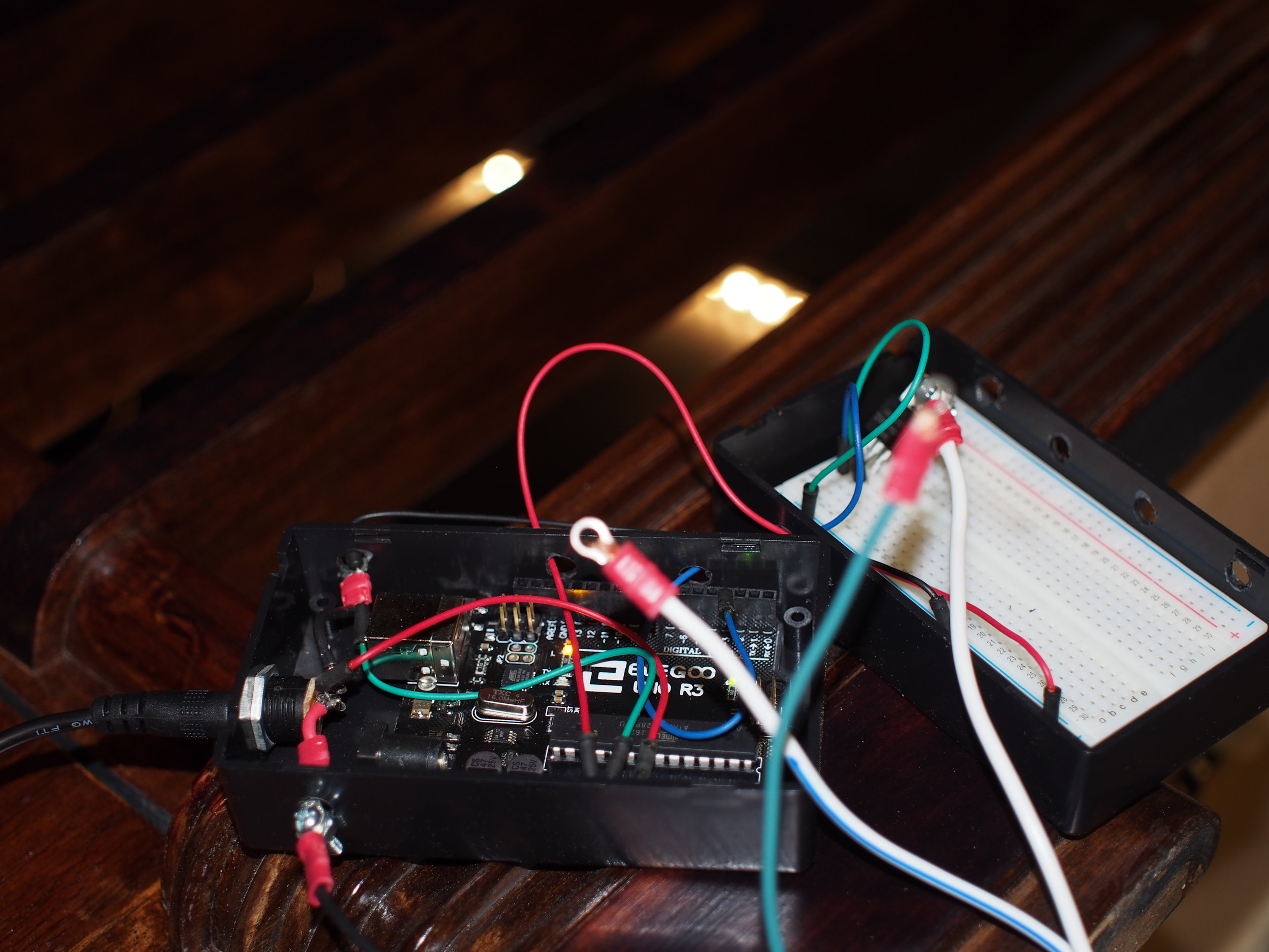
A test of the circuit with only one power LED connected
I bought a long-shaft potentiometer for the dial. At this late date, I realized the potentiometer for the dial needed to interface with the complicated three-part dial of the original radio, which combined a number of functions coaxially. I bought brass bushings which fit over the potentiometer shaft to preserve the ability of all three dials to spin.
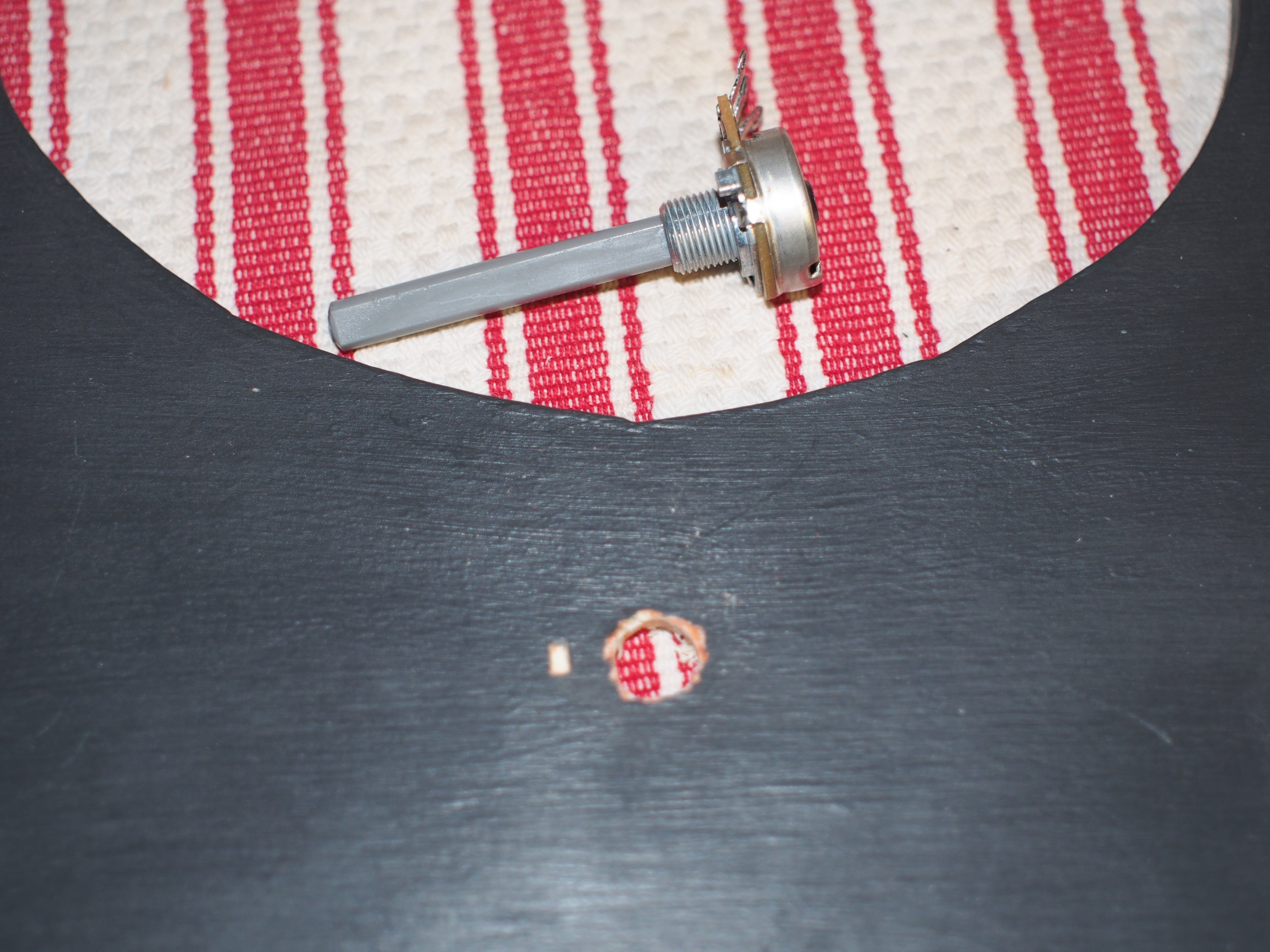
The long-shaft potentiometer, along with the panel I would mount it to
The brass bushing on the long-shaft potentiometer, which is mounted on the panel
I cut a panel out of 7/32" underlayment to mount the poteniometer. This will also be a place to mount buttons if I ever decide to use the radio buttons in the future. Bre painted that for me.
Another test circuit for the potentiometer
I ran 28 AWG leads from the potentiometer to the Arduino, on the theory I wanted room for the twelve buttons on the front later to run lead through the same holes in the cabinet. In retrospect, I regret my life choices. That wire was wayyy too fine for this work, and I redid it at least twice when it broke.

The final location of the Arduino

The power circuit, with four color channels. These are *almost* color-coded.
Everything all put together. Can you tell I'm not a cable-layout purist?
Once the circuit was assembled and tested, I drilled a hole in the potentiometer shaft for the last knob. That knob was cracked, so I epoxyed the shaft of an allen key into the knob and placed it into the drilled hole. We also replaced the broken glass with a new dome. I especially like how the glassware behind it looks with the LEDs on.

Almost done, just one last knob to put on!
The finished bar!
As I finish this, the bar cabinet sits behind me, softly glowing. I think it might need a pull for opening the door, but that is a project for another day.
Comments ()